
Why FastTrack?
Not Created Equal
Not all enclosed track conveyors are created equal. Although they all look pretty much the same, there are some fundamental engineering considerations that put one type of enclosed track conveyor miles ahead of the rest.
The True Limit
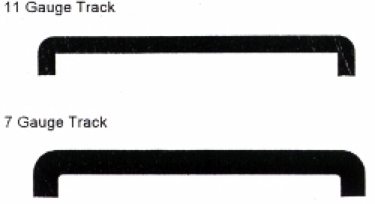
Ask enclosed track overhead conveyor owners what they think the chief limiting factor to long conveyor life is, and they answer the chain. In fact, the main limiting factor to long enclosed track conveyor life is the track. While chain is readily replaced, a badly worn track means replacing the conveyor.
A Lesson From Our Highways
When the various highway departments around the country found their roads were being destroyed by trucks carrying overly heavy loads what did they do? They legislated more wheels per truck. That decision was based on a concept called Point Loading. The weight of a truck's load is transferred to the road through the wheels. The amount of load transferred to any individual point in the road is reduced when there are more wheels. This same rule of spreading the load to avoid damaging or sinking through the supporting surface, is evidenced in snow shoes and in the large balloon tires often used on off-road bicycles.
The Source of Track Failure
It's well known that conveyor track starts to peen when point loads exceed 135 lb. That is, when any wheel is transferring more than 135 lb. of weight to any single point on the track. Like hot asphalt under truck wheels, the conveyor track surface starts to bulge in front of the chain wheels and molecules are shifted permanently off to the sides. Eventually, that portion of track where the wheels consistently make contact, becomes so thin it fails. The truly surprising thing about this phenomenon is that it is happening consistently on conveyors operating within the 750 lb. chain pull guidelines suggested by their manufacturers. This Point Loading problem is illustrated in the two small drawings which follow.
Spreading The Load
In Diagram 2, more wheels help to spread identical chain load over a greater area, such that point loading under these wheels is 40 percent lower. Now, this same principle applied internally to the chain, also saves it from damage. Each wheel in Diagram 2 bears a smaller load and will last longer even if made of the same material.
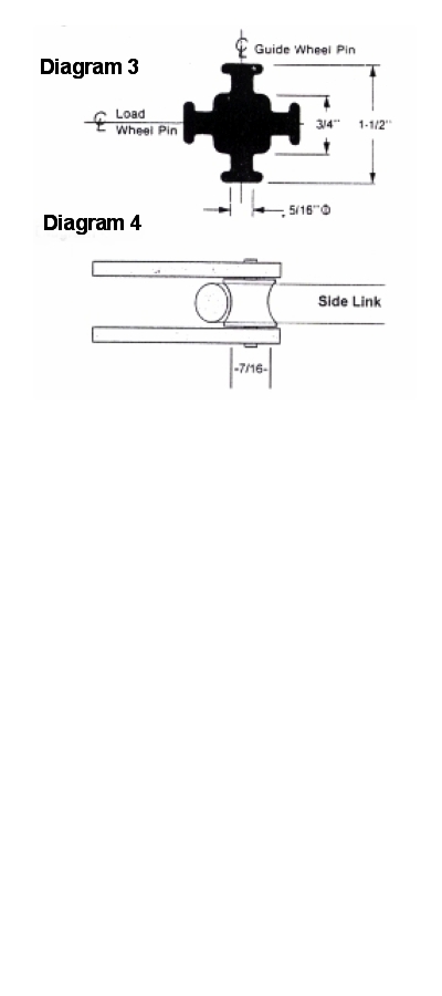
Point Loading Inside The Chain
Let's focus now, on some point loading considerations inside the chain itself. That portion of a chain link which engages the adjoining link also warrants closer scrutiny. Most enclosed track conveyor chains use a universal block and sliding holes to join the links and provide chain flex. (See Diagram 3) The diameter of the pins engaging the chain side links is barely 5/16 of an inch. This part is not machined, and still contains parting lines from the mold in which it was forged. The physical area actually engaging the slotted side link is so small and rough that early chain wear is a certainty.