
System Specifications
Load Centres
Cirrus 800 Series chain is comprised of alternating vertical load bearings and horizontal guide bearings. Load bearings are located on 8-inch nominal centres, thereby allowing loads to be arranged on any multiples of 8-inches.
Load Capacity
The maximum load that can be suspended from a single load point on the chain is 125-pounds. Loads of 250-pounds can be suspended when using a load bar that connects between 2-chain load points.
Chain Pull
Chain pull is the force required to overcome the rolling resistance of the conveyor chain. The chain pull on a given system is proportional to the individual load weights, load centres, quantity of elevation changes, quantity of horizontal curves and overall environment that the system operates in. An average system chain pull will typically range between 1.5% and 4% of the sum of the moving load. Maximum chain pull for a single caterpillar drive is 750-pounds.
Contact Cirrus for chain pull calculations that relate to your system.
Typical System Components
Chain & Attachments
Series 800 conveyor chain is constructed from precision machined bearings connected with a forged steel universal joint. A set of two vertical load bearings carry loads and roll on the bottom portion of the track. Horizontal bearings guide the chain horizontally within straight track and horizontal curved track sections.
Chain is shipped in 20-foot coils complete with connecting pin and roller.
A wide range of attachments are available that hook into the chain which allow for suspending loads. Some attachments swivel that remain perpendicular to the floor and others are ridged and hang perpendicular to the conveyor track. A variety of indexing hooks and swivel rotator bearings are available to allow loads to index at 90-degree intervals or rotate freely.
For loads that exceed the 125-pound hanging limit, a load bar can be used to distribute the load between two load bearings, raising the limit to 250-pounds.
Track & Accessories
Straight track is roll formed from a special high carbon steel and results in a wall thickness of 5/32". Track is finish painted medium blue and is available in 10 and 20-foot lengths. Stainless steel track is also available, providing long life in challenging environments such as parts washers.
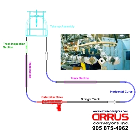
Each system will contain at least one chain installation gate which may also serve as an inspection port. This straight section of track is hinged on one side, allowing access to the chain. There is also an inspection gate that hinges on the top to provide access to the chain. The overall length of an inspection section is 27-inches.
Oven expansion joints are required in long straight runs of track to compensate for thermal expansion in ovens.
Horizontal Track Curves
Horizontal curves are formed from straight track sections and heat treated after forming. Two radii are available - 24-inch and 36-inch centreline radius. The most common are 24-inch centreline radius. Curves are typically shipped in segments of 30-degree, 45, 60, 90 and 180-degrees.
Vertical Track Curves
Vertical track curves are formed from straight track sections and heat treated after forming. In order to complete a change in elevation, two types of vertical curves are required. A lower vertical curve leads the chain from level to an incline and a top vertical curve takes the chain from an incline back to a horizontal position. Straight track situated between the vertical curves can be added to increase the overall incline or decline of the elevation change.
Two radii of vertical curves are available - 24-inch centreline radius and 36-inch radius. The most common are 24-inch centreline radius. Curves are typically shipped in segments of 30-degree, 45 and 90-degrees.
